|
本篇文章主要介绍如何采集并处理由BH1745NUC色彩传感器生成的RGB数据。
传感器 在第1部分中,我们讨论了如何使用DAC和一些负反馈来精确控制红色、绿色和蓝色LED的强度。我们现在可以使用RGB LED模块作为单像素显示器 - 即,通过操纵红色、绿色和蓝色光的混合,我们可以产生多种颜色。
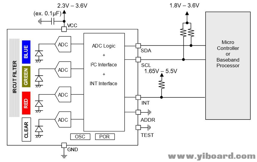
我们希望使用这个LED模块复制照亮RGB传感器的光线颜色。如第一篇文章中所述,我们使用由Rohm制造的BH1745NUC颜色传感器(以下简称为BH1745)。这实际上是一个令人印象深刻的设备封装非常小(大约2 mm×2 mm),这也是我们为这个项目使用定制设计PCB的一个原因。尽管体积小,但该部件具有广泛的功能,仅需少量外部组件。以下是数据表中的“典型应用电路”:

电路中需要光学滤波器、四个光电二极管、四个独立的16位ADC以及一些信号调制电路、一个I2C接口和一些中断逻辑,可用于在红色、绿色、蓝色或透明测量值超过时提醒微控制器或者低于可定制的阈值 。
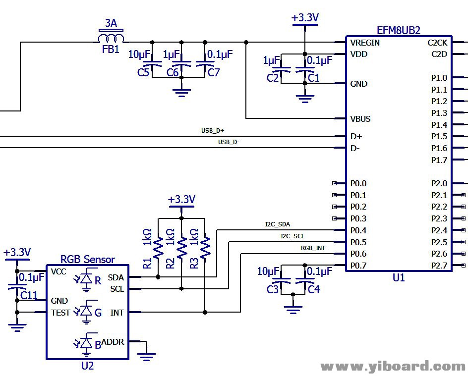
以下是原理图的相关部分:

收集数据 BH1745的数字部分包括一组21个8位寄存器。除了中断功能之外的所有交互 - 在微控制器和BH1745之间通过标准I2C事务写入或读取这些寄存器来完成。。这里我们将重点介绍BH1745的具体实现细节。
从BH1745控制和检索数据需要三种类型的I2C事务:写入、读取前读取和读取。 ● 写入:这些事务用于将数据加载到BH1745的寄存器库中。 slave-address-plus-R / nW字节后的第一个字节指定寄存器地址,然后后面的字节是要加载到寄存器中的数据。

● 读之前写入:如果您熟悉I2C协议,则您知道主机无法在一个事务中写入和读取数据。每个事务都定义为读或写。因此,我们不能使用单个事务来指示寄存器地址,然后从该寄存器读回数据。解决方案是两个独立的事务 - 首先我们将数据写入BH1745以告诉它我们想要读取哪个寄存器,然后我们跟进读取事务以从指定寄存器中检索数据。这个过程中的第一个事务就是我所说的read-before-read事务。 ● 读取:这些事务允许主机从读写前事务中传输的任何寄存器地址读取数据。

如您所见,读取事务不限于指定的寄存器地址。如果继续从BH1745读取字节,它将自动递增寄存器地址并从新寄存器发送数据。实际上,您可以使用写入事务执行相同的操作:

我通常避免自动递增功能,因为我重视保持简单原则,这在这里特别相关,因为BH1745的寄存器没有连续排列(即,无效寄存器地址混合在有效寄存器地址中)。但是,我在读取RGBC数据时会使用此功能 - 所有8个字节都是连续的(从地址0x50开始),使用16个单独的单字节事务频繁收集RGBC数据将是非常低效的(8个写入之前 - 读取和8读取)。
另请注意,可以使用重复启动条件(如上图所示)实现读前读和读事务,而不是停止条件,后跟启动条件。如果我们在I2C总线上有多个主设备,这将是更好的选择。但是在这个项目中,我们只有一个master,所以我们将再次调用keep-it-simple原则并使用典型的stop-then-start方法。
处理数据 RGBC数据从BH1745到达为四个16位字,如下所示:

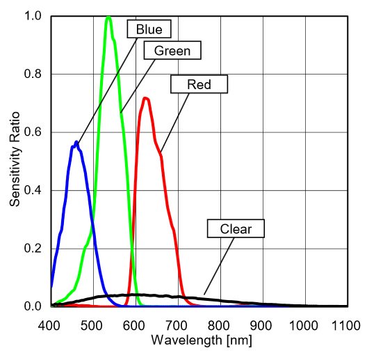
我们可以忽略这个项目的明确数据;我们需要做的就是将R、G和B字转换为8位值,我们可以使用这些值来控制R、G和B LED的强度。首先要意识到BH1745中的三个颜色探测器不是同样敏感的:

从该图可以看出,当G为1时,R约为0.72,B约为0.56。因此,我们需要将R和B值乘以适当的校正因子: CFR = 10.72 = 1.39,CFB = 10.56 = 1.79 现在我们需要以强调入射光的颜色特征的方式修改数据。我们的目标是“测量”颜色,无论照射光电探测器的光的总强度如何。因此,我们需要以一种标准化测量绝对值的方式缩放RGB值,同时保留相对值 - 换句话说,我们最大化整体强度,同时保持入射光中红色、绿色和蓝色的比例。为了实现这一点,我们将三次测量中的最高值乘以任何因子将该最高测量值增加到最大值,然后我们将另外两次测量值乘以相同的因子。此评论的代码摘录阐明了整个过程: - //extract the 16-bit R, G, and B values from the received data
- R_word = (I2C_RcvData[1] << 8) | I2C_RcvData[0];
- G_word = (I2C_RcvData[3] << 8) | I2C_RcvData[2];
- B_word = (I2C_RcvData[5] << 8) | I2C_RcvData[4];
- //apply correction factors based on the relative sensitivity of the three photodetectors
- R_intensity = R_word * 1.39;
- G_intensity = G_word * 1;
- B_intensity = B_word * 1.79;
- //determine which intensity is the highest of the three
- if(R_intensity >= G_intensity && R_intensity >= B_intensity)
- MaxIntensity = R_intensity;
- else if(G_intensity >= R_intensity && G_intensity >= B_intensity)
- MaxIntensity = G_intensity;
- else
- MaxIntensity = B_intensity;
- /*Now we scale each measurement into the range 0 to 100.
- * This preserves the relative ratios of the three
- * intensities but standardizes the absolute intensities.
- * Thus, the appearance of the LED module is
- * determined by the proportion of red, green,
- * and blue light, not by the overall intensity of
- * the incident light.*/
- R_scaled = (R_intensity/MaxIntensity)*100;
- G_scaled = (G_intensity/MaxIntensity)*100;
- B_scaled = (B_intensity/MaxIntensity)*100;
请注意,最终值被缩放,使得最大值为100。您可以从上一篇文章中回忆起DAC具有8位分辨率,因此我们可以高达255.那么为什么我要将LED强度限制为100而不是使用完整的8位范围?因为盯着这个高达20毫安的LED模块正在弄乱我的视线!光是如此聚焦和光谱纯净,似乎以加重的方式混淆眼睛。
详细步骤 以下是配置BH1745、收集数据、处理数据和更新DAC的整个过程。 1. 写入寄存器0x42以启用RGBC转换。 2. 延迟1秒(或测量之间的一些其他适当间隔)。 3. 写入寄存器地址0x50以准备读取RGBC数据。 4. 读取8字节的RGBC数据(对于这个项目,我们只需要前6个字节)。 5. 等到I2C事务完成。 6. 将16位RGB数据读入三个无符号16位变量。 7. 将这三个变量转换为浮点值,同时将每个变量乘以适当的校正因子。 8. 找到三者中的最大值,并如上所述缩放每个值;将结果存储在无符号的8位变量中。 9. 通过将8位值加载到适当的DAC通道来更新LED颜色。
固件 您可以打开“hwconf”文件以访问端口引脚和外设的配置详细信息。另请注意,这些源文件包含一些代码,直到我们合并USB连接时才需要这些代码。 以下是一些比较重要的代码段。 首先,main()函数: - int main(void) {
- unsigned char R_scaled, G_scaled, B_scaled;
- unsigned int R_word, G_word, B_word;
- float R_intensity, G_intensity, B_intensity, MaxIntensity;
- // Call hardware initialization routine
- enter_DefaultMode_from_RESET();
- //enable global interrupts
- IE_EA = 1;
- //tell the RGBC sensor to start performing measurements
- I2C_MasterWrite(RGBC_Tx_EnableConv);
- while (1)
- {
- Delay_10ms(100); //the LED is updated once per second
- //load the proper register address (for reading) into the RGBC sensor
- I2C_MasterWrite(RGBC_Tx_SetReadRGBC);
- //read the RGBC data
- I2C_MasterRead(RGBC_Rx_RGBC);
- //wait until the read transaction is complete
- while(I2C_State != MstR_DATA_READY);
- I2C_State = IDLE;
- //extract the 16-bit R, G, and B values from the received data
- R_word = (I2C_RcvData[1] << 8) | I2C_RcvData[0];
- G_word = (I2C_RcvData[3] << 8) | I2C_RcvData[2];
- B_word = (I2C_RcvData[5] << 8) | I2C_RcvData[4];
- //apply correction factors based on the relative sensitivity of the three photodetectors
- R_intensity = R_word * 1.39;
- G_intensity = G_word * 1;
- B_intensity = B_word * 1.79;
- //determine which intensity is the highest of the three
- if(R_intensity >= G_intensity && R_intensity >= B_intensity)
- MaxIntensity = R_intensity;
- else if(G_intensity >= R_intensity && G_intensity >= B_intensity)
- MaxIntensity = G_intensity;
- else
- MaxIntensity = B_intensity;
- /*Now we scale each measurement into the range 0 to 100.
- * This preserves the relative ratios of the three
- * intensities but standardizes the absolute intensities.
- * Thus, the appearance of the LED module is
- * determined by the proportion of red, green,
- * and blue light, not by the overall intensity of
- * the incident light.*/
- R_scaled = (R_intensity/MaxIntensity)*100;
- G_scaled = (G_intensity/MaxIntensity)*100;
- B_scaled = (B_intensity/MaxIntensity)*100;
- /* This can be used to turn off the LED if the measured
- * light intensity is too low. This helps to avoid distracting
- * color changes related to irrelevant RGB variations detected
- * during low-intensity lighting conditions. This functionality
- * was used with the "Christmas lights" demonstration to make
- * the LED turn off when the sensor was not illuminated by one
- * of the lights.*/
- if(MaxIntensity < 100)
- {
- R_scaled = 0;
- G_scaled = 0;
- B_scaled = 0;
- }
- //update each DAC channel with the scaled values
- UpdateDAC(DAC_RGB_R, R_scaled);
- UpdateDAC(DAC_RGB_G, G_scaled);
- UpdateDAC(DAC_RGB_B, B_scaled);
- }
- }
此代码配置并启动I2C事务: - unsigned char I2C_SlaveAddr; //global variable for current slave address
- unsigned char I2C_NumReadBytes; //number of bytes to be read
- unsigned char idata *I2C_WriteBufferPtr; //pointer to bytes to be transmitted
- unsigned char I2C_FinalWriteAddress; //the ISR uses this to determine which byte is the final byte
- /*These "transaction arrays" contain all the information needed for a particular I2C transaction*/
- //write to register address 0x42 to enable RGBC conversions and keep the gain at default (1x)
- unsigned char idata RGBC_Tx_EnableConv[4] = {RGB_SENS_ADDR, 2, 0x42, 0x10};
- //write to register address 0x42 to enable RGBC conversions and set the gain to 16x
- //(so far it appears that it is best to leave the gain at 1x)
- unsigned char idata RGBC_Tx_EnableConv_16x[4] = {RGB_SENS_ADDR, 2, 0x42, 0x12};
- //set the read address to 0x50, which is the beginning of the registers that hold RGBC data
- unsigned char idata RGBC_Tx_SetReadRGBC[3] = {RGB_SENS_ADDR, 1, 0x50};
- //read RGBC data (after setting the read address using RGBC_Tx_SetReadRGBC )
- unsigned char idata RGBC_Rx_RGBC[3] = {RGB_SENS_ADDR, RGBC_DATA_LEN};
- void I2C_MasterWrite(unsigned char* PtrtoCmdBuffer) //function argument is simply the name of the transaction array
- {
- //ensure that we are not interrupting an ongoing transaction
- while(I2C_State != IDLE);
- I2C_State = MstW_STA_SENT; //first state is "start condition generated"
- I2C_SlaveAddr = PtrtoCmdBuffer[0]; //copy the slave address from the transaction array to the global variable
- I2C_WriteBufferPtr = PtrtoCmdBuffer + 2; //set the address of the first data byte in the transaction array
- I2C_FinalWriteAddress = I2C_WriteBufferPtr + (PtrtoCmdBuffer[1] - 1); //set the final address based on the number of bytes to be transmitted
- SFRPAGE = SMB0_PAGE;
- SMB0CN0_STA = 1; //initiate the transaction by setting the start-condition bit
- }
- void I2C_MasterRead(unsigned char* PtrtoCmdBuffer) //function argument is simply the name of the transaction array
- {
- //ensure that we are not interrupting an ongoing transaction
- while(I2C_State != IDLE);
- I2C_State = MstR_STA_SENT; //first state is "start condition generated"
- I2C_SlaveAddr = PtrtoCmdBuffer[0]; //copy the slave address from the transaction array to the global variable
- I2C_NumReadBytes = PtrtoCmdBuffer[1]; //copy the number of bytes to be read from the transaction array to the global variable
- SFRPAGE = SMB0_PAGE;
- SMB0CN0_STA = 1; //initiate the transaction by setting the start-condition bit
- }
|