|
在本篇帖子中,我们将探索红外技术的潜力以及如何将其与Arduino开发板一起使用。红外通信是电子设备中允许无线信息交换的常见功能。从遥控器到自动门,红外技术无处不在。了解红外通信的原理并学习如何使用它将会开辟广泛的可能性。本文将帮助您使用Arduino开发板发送和接收红外信号。我们将介绍红外通信的基础知识,包括不同的协议和代码,以及帮助您入门的实际示例。
什么是红外通信? 红外通信是一种常见、廉价且简单的无线通信技术。红外光与可见光非常相似,只是它的波长稍长。这意味着红外辐射对人眼是不可见的,使其适合数据交换。
红外通信仅限于短距离,并且需要直接视线。它也不能穿过墙壁。
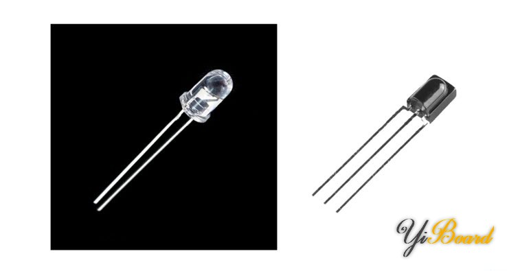
由于红外的这些限制,很难跟踪通信。事实上,红外设备之间的通信通常是一对一的。因此,以这种方式传输的数据通常不加密。
当您使用红外无线控制时,红外光谱中的LED用于将数据传输到接收器。但我们周围有各种红外源。太阳、灯泡或任何其他产生热量的东西在红外光谱中都非常明亮。因此,红外接收器必须能够区分遥控器的信号和环境红外信号。为此,我们使用调制的红外信号。调制信号就像为数据分配一个模式以确保接收器可以识别它。
红外通信的常见调制是38kHz 调制。38kHz信号波的自然来源很少,因此使用该频率的红外发射器将与环境红外波不同。当您按下遥控器上的某个键时,红外发射器的LED将在几分之一秒内快速闪烁,将编码数据传输到接收器。

通过红外传输的数据(除了其主频率38kHz 外)还有自己的协议。例如,NEC 协议(曾被日本家电制造商广泛使用)以以下格式传输数据。
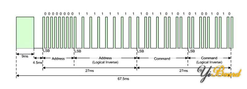
到目前为止,我们已经了解了红外发射器和接收器以及如何在它们之间进行通信。现在,让我们看看如何使用这种方法在两个Arduino开发板之间进行通信并在它们之间发送和接收命令。
所需的组件 ● Arduino UNO R3开发板 ● 38KHz红外接收器模块 ● 红外发射器模块 ● 公对母跳线
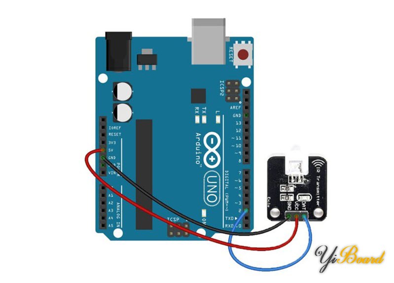
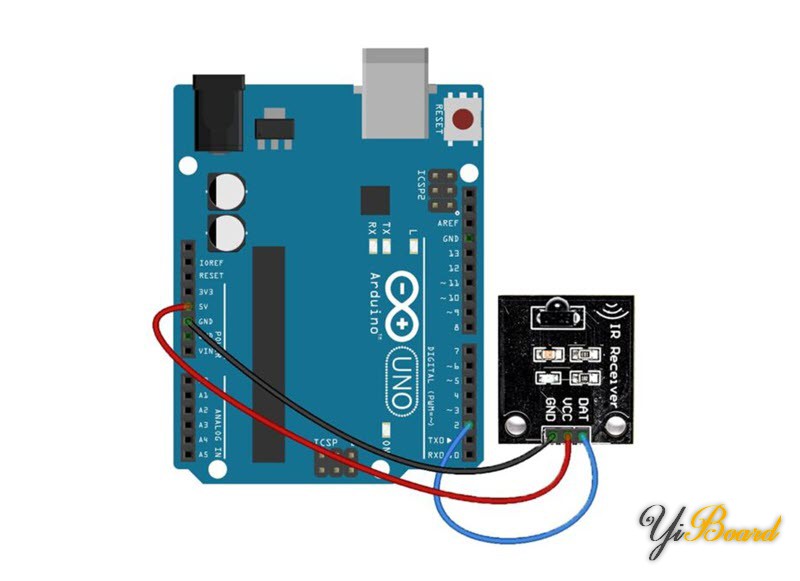
两个Arduino开发板之间的红外通信的硬件电路 如前所述,我们将使用Arduino搭建两个独立的电路。第一个电路使用38kHz红外传感器接收红外信号,并使用Arduino控制器解释输入信号。第二个电路包括一个红外发射器LED模块和一个Arduino控制器,用于将红外代码发送到接收器。
以下是这是发射器的电路:
以下是接收器的电路:
红外发射器的Arduino代码 首先,下载IRremote库并安装。然后在Arduino IDE软件中复制并粘贴以下代码。
- /*
- modified on AUG 23, 2023
- */
- #include <Arduino.h>
- #define DISABLE_CODE_FOR_RECEIVER // Disables restarting receiver after each send. Saves 450 bytes program memory and 269 bytes RAM if receiving functions are not used.
- //#define SEND_PWM_BY_TIMER // Disable carrier PWM generation in software and use (restricted) hardware PWM.
- //#define USE_NO_SEND_PWM // Use no carrier PWM, just simulate an active low receiver signal. Overrides SEND_PWM_BY_TIMER definition
- /*
- This include defines the actual pin number for pins like IR_RECEIVE_PIN, IR_SEND_PIN for many different boards and architectures
- */
- #include "PinDefinitionsAndMore.h"
- #include <IRremote.hpp> // include the library
- void setup() {
- pinMode(LED_BUILTIN, OUTPUT);
- Serial.begin(115200);
- pinMode(10, INPUT_PULLUP);
- pinMode(11, INPUT_PULLUP);
- pinMode(12, INPUT_PULLUP);
- Serial.print(F("Send IR signals at pin ")); //Printouts the IR send pin used in the chip you want.
- Serial.println(IR_SEND_PIN);
- // IrSender.begin(); // Start with IR_SEND_PIN as send pin and if NO_LED_FEEDBACK_CODE is NOT defined, enable feedback LED at default feedback LED pin
- IrSender.begin(DISABLE_LED_FEEDBACK); // Start with IR_SEND_PIN as send pin and disable feedback LED at default feedback LED pin
- }
- /*
- Set up the data to be sent.
- For most protocols, the data is build up with a constant 8 (or 16 byte) address
- and a variable 8 bit command.
- There are exceptions like Sony and Denon, which have 5 bit address.
- */
- uint8_t saddress = 0;
- uint8_t sCommand = 0;
- uint8_t sRepeats = 0;
- void loop() {
- if (digitalRead(10) == LOW)
- {
- saddress = 0x00;
- sCommand = 0x10;
- sRepeats = 1;
- }
- else if (digitalRead(11) == LOW)
- {
- saddress = 0x01;
- sCommand = 0x20;
- sRepeats = 1;
- }
- else if (digitalRead(12) == LOW)
- {
- saddress = 0x02;
- sCommand = 0x30;
- sRepeats = 1;
- }
- if (digitalRead(10) == LOW || digitalRead(11) == LOW || digitalRead(12) == LOW)
- {
- /*
- Print current send values
- */
- Serial.println();
- Serial.print(F("Send now: address=0x")); Serial.print(saddress, HEX);
- Serial.print(F("command=0x")); Serial.print(sCommand, HEX);
- Serial.print(F(", repeats=")); Serial.print(sRepeats);
- Serial.println();
- Serial.println(F("Send standard LG with 8 bit address"));
- Serial.flush();
- IrSender.sendLG(saddress, sCommand, sRepeats);
- }
- delay(1000); // delay must be greater than 5 ms (RECORD_GAP_MICROS), otherwise the receiver sees it as one long signal
- }
该代码读取Arduino引脚10、11和12的状态,如果其中任何一个连接到GND,它会传输一条包含不同命令和不同地址的消息。使用的协议是LG。通过更改sRepeats变量,您可以设置每次传输的消息重复次数。
传输的数据也可以在串口监视器中查看。为此,您需要在Arduino IDE软件中打开,然后将波特率设置为115200。
红外接收器的Arduino代码 在Arduino IDE软件中复制并粘贴以下代码。
- /*
- modified on AUG 23, 2023
- */
- /*
- * Specify which protocol(s) should be used for decoding.
- * If no protocol is defined, all protocols (except Bang&Olufsen) are active.
- * This must be done before the #include <IRremote.hpp>
- */
- //#define DECODE_DENON // Includes Sharp
- //#define DECODE_JVC
- //#define DECODE_KASEIKYO
- //#define DECODE_PANASONIC // alias for DECODE_KASEIKYO
- #define DECODE_LG
- #define DECODE_NEC // Includes Apple and Onkyo
- //#define DECODE_SAMSUNG
- //#define DECODE_SONY
- //#define DECODE_RC5
- //#define DECODE_RC6
- //#define DECODE_BOSEWAVE
- //#define DECODE_LEGO_PF
- //#define DECODE_MAGIQUEST
- //#define DECODE_WHYNTER
- //#define DECODE_FAST
- //#define DECODE_DISTANCE_WIDTH // Universal decoder for pulse distance width protocols
- //#define DECODE_HASH // special decoder for all protocols
- //#define DECODE_BEO // This protocol must always be enabled manually, i.e. it is NOT enabled if no protocol is defined. It prevents decoding of SONY!
- //#define DEBUG // Activate this for lots of lovely debug output from the decoders.
- //#define RAW_BUFFER_LENGTH 180 // Default is 112 if DECODE_MAGIQUEST is enabled, otherwise 100.
- #include <Arduino.h>
- /*
- * This include defines the actual pin number for pins like IR_RECEIVE_PIN, IR_SEND_PIN for many different boards and architectures
- */
- #include "PinDefinitionsAndMore.h"
- #include <IRremote.hpp> // include the library
- void setup() {
- Serial.begin(115200);
- // Start the receiver and if not 3. parameter specified, take LED_BUILTIN pin from the internal boards definition as default feedback LED
- IrReceiver.begin(IR_RECEIVE_PIN, ENABLE_LED_FEEDBACK);
- Serial.print(F("Ready to receive IR signals of protocols: "));
- printActiveIRProtocols(&Serial);
- Serial.println(F("at pin " STR(IR_RECEIVE_PIN))); //Printouts the IR receive pin used in the chip you want.
- }
- void loop() {
- /*
- * Check if received data is available and if yes, try to decode it.
- * Decoded result is in the IrReceiver.decodedIRData structure.
- */
- if (IrReceiver.decode()) {
- /*
- * Print a short summary of received data
- */
- IrReceiver.printIRResultShort(&Serial);
- IrReceiver.printIRSendUsage(&Serial);
- if (IrReceiver.decodedIRData.protocol == UNKNOWN) {
- Serial.println(F("Received noise or an unknown (or not yet enabled) protocol"));
- // We have an unknown protocol here, print more info
- IrReceiver.printIRResultRawFormatted(&Serial, true);
- }
- Serial.println();
- /*
- * !!!Important!!! Enable receiving of the next value,
- * since receiving has stopped after the end of the current received data packet.
- */
- IrReceiver.resume(); // Enable receiving of the next value
- /*
- * Finally, check the received data and perform actions according to the received command
- */
- if (IrReceiver.decodedIRData.command == 0x10) {
- // do something
- Serial.println("received command 10");
- } else if (IrReceiver.decodedIRData.command == 0x20) {
- // do something else
- Serial.println("received command 20");
- } else if (IrReceiver.decodedIRData.command == 0x30) {
- // do something else
- Serial.println("received command 30");
- }
- }
- }
在该代码中,Arduino开发板等待接收红外信号,如果接收到的数据格式正确,则根据其指令和地址在串口监视器上打印一条消息。
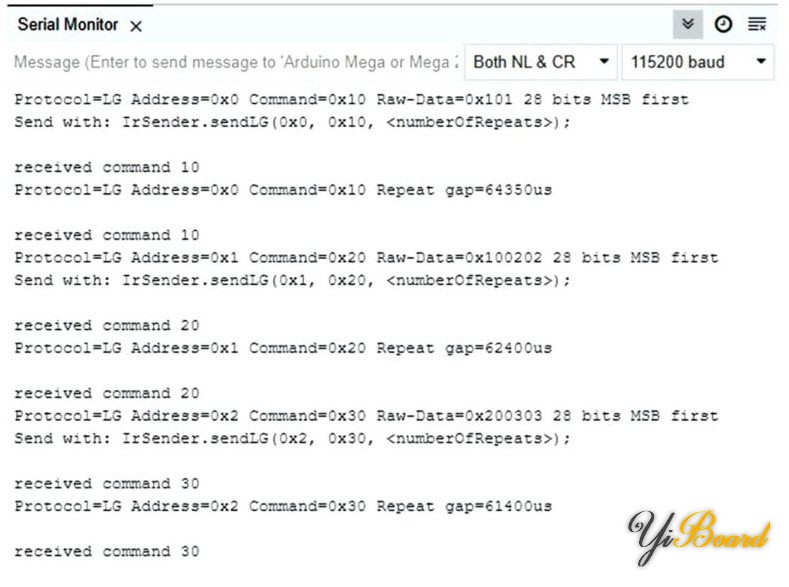
Arduino红外通信示例测试 对两个Arduino开发板进行编程后,确保发射器上的LED和红外接收器上的二极管彼此相对。现在,如果您将发射器板上的10、11或12引脚之一连接到GND,则相应的地址和命令将传输到接收器。
您可以在发射器和接收器的串行监视器上分别查看发送和接收的数据。在这里,我们通过将引脚10、11 或12连接到GND 来测试所有三种模式。如您所见,每个引脚对应的命令都已发送和接收。
|  |手机版|YiBoard一板网
( 冀ICP备18020117号 )