风筝
发表于: 2022-6-20 17:45:16 | 显示全部楼层

您是否想在屋内听到距离您数公里远发生的事情,或者只需一个电话即可启动花园中的自动喷水系统;那么SIM800L GSM/GPRS模块可以作为您开始使用物联网的坚实起点!


SIM800L GSM/GPRS模块是一款微型GSM调制解调器,可集成到众多物联网项目中。您可以使用此模块完成普通手机可以完成的几乎任何事情,比如收发短信、接打电话、通过GPRS、TCP/IP等方式连接到互联网!最重要的是,该模块支持四频GSM/GPRS 网络,这意味着它几乎可以在世界的任何地方工作。


SIM800L GSM/GPRS模块硬件概述

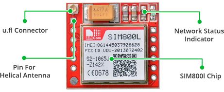
该模块的主要组件是来自SimCom公司的GSM蜂窝芯片SIM800L。该芯片的工作电压为3.4V至 4.4V,这使其可以直接使用锂聚合物电池供电。在没有大量空间的项目中,该模块是一个不错的选择。
SIM800L-Module-Hardware-Overview-LED-Indicator-u.fl-Connector-Helical-Antenna.jpg


所有SIM800L GSM芯片的必要数据引脚都引出到一个0.1英寸间距的插头。这里包括通过UART与微控制器通信所需的引脚。该模块支持从1200bps到115200bps的波特率,并且具有自动波特率检测功能。


该模块需要外部天线连接到网络。该模块通常带有螺旋天线,并直接焊接到PCB上的NET引脚。该模块还带有一个U.FL连接器,可以将天线从电路板引出。

SIM800L-Module-Hardware-Overview-Micro-SIM-Socket-Direction-to-Insert-SIM.jpg


在模块的背面有一个SIM卡插槽,任何已激活的2G Micro SIM卡都可以正常工作。在SIM卡座的表面通常刻有SIM卡插入的正确方向。


该模块的尺寸仅为1平方英寸,但在其小巧的外形中包含了惊人的功能。下面列出了其中一些功能:

●    支持四频:GSM850、EGSM900、DCS1800 和 PCS1900

●    使用任意2G SIM卡连接到任何全球GSM网络

●    使用外部8Ω扬声器和驻极体麦克风拨打和接听语音电话

●    发送和接收短信

●    发送和接收GPRS数据(TCP/IP、HTTP等)

●    扫描和接收FM调频广播

●    发射功率:

     ●    GSM850 4 级 (2W)

     ●    DCS1800 1 级 (1W)

●    基于串口的AT指令集

●    用于蜂窝天线的 u.FL 连接器

●    支持Micro SIM卡


LED状态指示灯

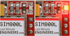
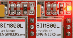
在SIM800L模块的右上方​​有一个LED灯,用于指示蜂窝网络的状态。它会以不同的频率闪烁以指示它所处的状态:
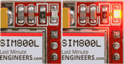
Netlight-LED-Blinking-Network-Connection-Established.gif

每1秒闪烁一次:该模块正在运行,但尚未连接到蜂窝网络。


Netlight-LED-Blinking-Active-GPRS-Connection.gif

每2秒闪烁一次:请求的GPRS数据连接处于活动状态。


Netlight-LED-Blinking-Finding-Network-Connection.gif

每3秒闪烁一次:该模块已与蜂窝网络建立联系,可以发送/接收语音电话和短信。


天线选择

该模块需要天线才能用于任何类型的语音或数据通信以及一些SIM命令。因此,选择天线可能是至关重要的事情。有两种方法可以将天线添加到SIM800L模块。


第一个是选择螺旋GSM天线,通常与模块一起提供并直接焊接到PCB上的NET引脚。该天线对于需要节省空间但难以获得连接的项目非常有用,尤其是在您的项目在室内时。
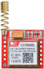
SIM800L-GSM-Module-with-Helical-Antenna.jpg


第二种是任何3dB的GSM天线以及U.FL转SMA适配器。您可以将此天线卡扣到位于模块左上角的小型U.FL连接器上。这种类型的天线具有更好的性能,并且可以将您的模块放在金属外壳内——只要天线在外面。
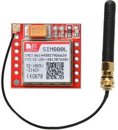
SIM800L-GSM-Module-with-2dBi-Duck-Antenna.jpg


SIM800L模块供电

让SIM800L模块工作的最重要部分之一是为其提供足够的电流。


根据SIM800L所处的状态,它可能是一个相对耗电的设备。在传输突发期间,模块消耗的最大电流约为2A。它通常不会拉那么多,但在通话期间可能需要大约 216 毫安,在网络传输期间可能需要80毫安。数据表中的这张图表总结了功耗值:

模式
频率
电流功耗
掉电模式
60 uA
睡眠模式
1 mA
待机模式
18 mA
通话
GSM850
199 mA
EGSM900
216 mA
DCS1800
146 mA
PCS1900
131 mA
GPRS
453 mA
传输突发
2 A

由于SIM800L模块没有带板载稳压器,因此需要外部电源调节到3.4V至4.4V(理想 4.1V)之间的电压。电源也应该能够提供2A的浪涌电流,否则模块将一直关机。以下是您可以考虑为GSM模块供电的一些选择。


3.7v锂聚合物电池

锂聚合物电池的一个很酷的地方是它们的电压通常在3.7V – 4.2V的范围内,非常适合SIM800L模块。采用1200mAh或更大容量的锂聚合物电池都可以,因为即使在2 A尖峰期间它也能提供正确的电压范围。

1200mAh-LiPo-Battery.jpg


DC-DC降压转换器

任何额定电流为2A的DC-DC 降压转换器(如 LM2596)都可以工作。这些比LM317或LM338等线性稳压器效率更高。
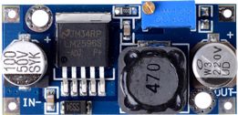
LM2596-DC-DC-Buck-Converter.jpg


警告:您应该非常小心,不要在VCC之前断开GND,并且始终在连VCC之前连接GND。否则模块可以使用低压串行引脚作为接地,并且会立即被破坏。


SIM800L GSM模块引脚

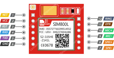
SIM800L模块共有12个引脚用于连接外部组件。引脚排列如下:
SIM800L-GSM-Module-Pinout.jpg


●    NET 网络引脚,可以在这里焊接随模块提供的螺旋天​​线。

●    VCC 为模块供电。可以是3.4V到4.4V之间的任何电压。请记住将其连接到5V引脚可能会损坏您的模块!它甚至不能在 3.3 V 上运行!外部电源(如锂聚合物电池或额定3.7V 2A的DC-DC降压转换器)可以工作。

●    RST(复位)是一个硬复位引脚。如果您将模块置于不良空间,请将此引脚拉低100毫秒以执行硬复位。

●    RxD(接收器)引脚用于串行通信。

●    TxD(发送器)引脚用于串行通信。

●    GND 是接地引脚,需要连接到Arduino上的GND引脚。

●    RING 引脚用作振铃指示器。它基本上是模块的“中断”输出引脚。它默认为高电平,并在收到电话时脉冲低电平 120 毫秒。它还可以配置为在收到短信时发出脉冲。

●    DTR 引脚激活/停用睡眠模式。将其拉高将使模块进入睡眠模式,禁用串行通信。将其拉低将唤醒模块。

●    MIC± 是差分麦克风输入。两个麦克风引脚可以直接连接到这些引脚。

●    SPK± 是一个差分扬声器接口。扬声器的两个引脚可以直接绑在这两个引脚上。


硬件链接 - SIM800L GSM模块连接到 Arduino UNO开发板

现在我们了解了有关该模块的所有信息,我们可以开始将它连接到Arduino开发板!


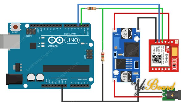
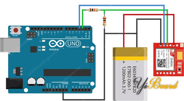
首先焊接/连接天线,将激活的Micro SIM卡插入插槽。现在,将模块上的Tx引脚连接到Arduino上的数字引脚#3,因为我们将使用软件串口与模块通信。


我们不能直接将模块上的Rx引脚连接到Arduino的数字引脚,因为Arduino Uno使用5V GPIO,而SIM800L模块使用 3.3V 电平逻辑并且不支持 5V。这意味着来自 Arduino Uno 的 Tx 信号必须降压到 3.3V,以免损坏 SIM800L 模块。有几种方法可以做到这一点,但最简单的方法是使用简易电阻分压器。 在SIM800L的Rx和Arduino D2之间连接10K 电阻,然后SIM800L的Rx和GND之间连接20K电阻,这样可以正常工作。


现在我们剩下的是用于为模块供电的引脚。由于您有多种启动模块的选择,我们提供了两个示例示意图。一种使用1200mAh 锂电池,另一种使用 LM2596 DC-DC 降压转换器。
Arduino-Wiring-Fritzing-Connections-with-SIM800L-GSM-GPRS-Module-3.7V-LiPo-Battery.jpg


Arduino-Wiring-Fritzing-Connections-with-SIM800L-GSM-GPRS-Module-LM2596.jpg


注意事项:如果您使用LM2596降压转换器为模块供电,请记住将电路中的所有接地共用。


一切就绪后,我们就可以编写代码了!

跳转到指定楼层
风筝
发表于: 2022-6-21 09:33:52 | 显示全部楼层

Arduino代码 – 测试AT指令

为了发送AT命令实现与SIM800L模块之间的通信,我们将使用串口监视器。下面的草图代码将使Arduino能够通过串口监视器上与SIM800L模块进行通信。在我们继续详细讲解代码之前,将您的Arduino开发板连接到计算机,编译以下代码并将其上传到 Arduino。


打开串口监视器后,请确保已勾选“Both NL & CR”选项!

  1. #include <SoftwareSerial.h>

  2. //Create software serial object to communicate with SIM800L
  3. SoftwareSerial mySerial(3, 2); //SIM800L Tx & Rx is connected to Arduino #3 & #2

  4. void setup()
  5. {
  6.   //Begin serial communication with Arduino and Arduino IDE (Serial Monitor)
  7.   Serial.begin(9600);
  8.   
  9.   //Begin serial communication with Arduino and SIM800L
  10.   mySerial.begin(9600);

  11.   Serial.println("Initializing...");
  12.   delay(1000);

  13.   mySerial.println("AT"); //Once the handshake test is successful, it will back to OK
  14.   updateSerial();
  15.   mySerial.println("AT+CSQ"); //Signal quality test, value range is 0-31 , 31 is the best
  16.   updateSerial();
  17.   mySerial.println("AT+CCID"); //Read SIM information to confirm whether the SIM is plugged
  18.   updateSerial();
  19.   mySerial.println("AT+CREG?"); //Check whether it has registered in the network
  20.   updateSerial();
  21. }

  22. void loop()
  23. {
  24.   updateSerial();
  25. }

  26. void updateSerial()
  27. {
  28.   delay(500);
  29.   while (Serial.available())
  30.   {
  31.     mySerial.write(Serial.read());//Forward what Serial received to Software Serial Port
  32.   }
  33.   while(mySerial.available())
  34.   {
  35.     Serial.write(mySerial.read());//Forward what Software Serial received to Serial Port
  36.   }
  37. }
复制代码

该草图首先包含SoftwareSerial.h库,并初始化SIM800L模块的Tx和Rx连接到的Arduino引脚。

  1. #include <SoftwareSerial.h>

  2. //Create software serial object to communicate with SIM800L
  3. SoftwareSerial mySerial(3, 2); //SIM800L Tx & Rx is connected to Arduino #3 & #2
复制代码

setup()函数中:我们以波特率9600初始化Arduino与Arduino IDE以及SIM800L模块之间的串口通信。

  1. //Begin serial communication with Arduino and Arduino IDE (Serial Monitor)
  2.   Serial.begin(9600);
  3.   
  4.   //Begin serial communication with Arduino and SIM800L
  5.   mySerial.begin(9600);
复制代码

现在我们已经建立了基础的连接,然后将尝试通过发送AT命令与SIM800L模块进行通信。

AT - 最基本的AT指令。它还初始化自动波特率。如果它有效,您应该看到AT字符回显然后OK!然后,您可以发送一些命令来查询模块并获取有关它的信息,例如

AT+CSQ - 检查信号强度,第一个#是dB强度,应该高于5左右。越高越好。当然,这取决于您的天线和位置!

AT+CCID – 获取SIM卡的卡号,这测试SIM卡是否正常,您可以验证该号码是否写在卡上。

AT+CREG? - 检查您是否已在网络上注册。第二个# 应该是1或 5。1 表示您已注册到家庭网络,5 表示您在漫游网络。除了这两个数字外,表明您没有注册到任何网络。

  1.   mySerial.println("AT"); //Once the handshake test is successful, it will back to OK
  2.   updateSerial();
  3.   mySerial.println("AT+CSQ"); //Signal quality test, value range is 0-31 , 31 is the best
  4.   updateSerial();
  5.   mySerial.println("AT+CCID"); //Read SIM information to confirm whether the SIM is plugged
  6.   updateSerial();
  7.   mySerial.println("AT+CREG?"); //Check whether it has registered in the network
  8.   updateSerial();
复制代码

loop()函数中,我们调用了名为 updateSerial() 的自定义函数,它持续等待来自串口监视器的任何输入,并通过D2引脚(模块的Rx)将其发送到SIM800L模块。如果SIM800L模块有任何响应,它还会连续读取D3引脚(模块的 Tx)。

  1. void updateSerial()
  2. {
  3.   delay(500);
  4.   while (Serial.available())
  5.   {
  6.     mySerial.write(Serial.read());//Forward what Serial received to Software Serial Port
  7.   }
  8.   while(mySerial.available())
  9.   {
  10.     Serial.write(mySerial.read());//Forward what Software Serial received to Serial Port
  11.   }
  12. }
复制代码

您应该在串口监视器上看到以下输出。

SIM800L-GSM-Module-Basic-AT-Commands-on-Arduino.png


现在您可以通过串口监视器发送任何命令,如下所示,提供有关网络连接和电池状态的更多信息:

ATI – 获取模块名称和版本

AT+COPS?  –  检查您是否已连接到网络,在本例中为 BSNL

AT+COPS=? – 返回网络中存在的运营商列表。

AT+CBC – 将返回电池状态。第二个数字是 % 电量(在本例中为 93%),第三个数字是以 mV 为单位的实际电压(在本例中为 3.877 V)

SIM800L-GSM-Module-Network-Connection-AT-Commands-on-Arduino.png

回复

使用道具 举报

风筝
发表于: 2022-6-21 10:07:13 | 显示全部楼层

Arduino代码 – 发送短信

让我们继续讨论有趣的事情。我们对Arduino进行编程,实现向您希望的任何电话号码发送短信。在尝试草图之前,您需要输入电话号码。搜索字符串 ZZxxxxxxxxxx 并将 ZZ 替换为国家代码,将 xxxxxxxxxx 替换为 11位电话号码。

  1. #include <SoftwareSerial.h>

  2. //Create software serial object to communicate with SIM800L
  3. SoftwareSerial mySerial(3, 2); //SIM800L Tx & Rx is connected to Arduino #3 & #2

  4. void setup()
  5. {
  6.   //Begin serial communication with Arduino and Arduino IDE (Serial Monitor)
  7.   Serial.begin(9600);
  8.   
  9.   //Begin serial communication with Arduino and SIM800L
  10.   mySerial.begin(9600);

  11.   Serial.println("Initializing...");
  12.   delay(1000);

  13.   mySerial.println("AT"); //Once the handshake test is successful, it will back to OK
  14.   updateSerial();

  15.   mySerial.println("AT+CMGF=1"); // Configuring TEXT mode
  16.   updateSerial();
  17.   mySerial.println("AT+CMGS="+ZZxxxxxxxxxx"");//change ZZ with country code and xxxxxxxxxxx with phone number to sms
  18.   updateSerial();
  19.   mySerial.print("Last Minute Engineers | lastminuteengineers.com"); //text content
  20.   updateSerial();
  21.   mySerial.write(26);
  22. }

  23. void loop()
  24. {
  25. }

  26. void updateSerial()
  27. {
  28.   delay(500);
  29.   while (Serial.available())
  30.   {
  31.     mySerial.write(Serial.read());//Forward what Serial received to Software Serial Port
  32.   }
  33.   while(mySerial.available())
  34.   {
  35.     Serial.write(mySerial.read());//Forward what Software Serial received to Serial Port
  36.   }
  37. }
复制代码

除了下面的代码片段外,该草图几乎与之前相同。建立连接后,我们发送以下 AT 命令:

AT+CMGF=1 – 选择 SMS 消息格式为文本。默认格式为协议数据单元 (PDU)

AT+CMGS=+ZZxxxxxxxxxx – 向指定的电话号码发送短信。输入的文本消息后跟“Ctrl+z”字符被视为 SMS。 ‘Ctrl+z’ 实际上是 ASCII 表中描述为 ‘substitute’ 的第 26 个非打印字符。因此,我们需要在发送消息后发送 26 (1A)。

  1.   mySerial.println("AT+CMGF=1"); // Configuring TEXT mode
  2.   updateSerial();
  3.   mySerial.println("AT+CMGS="+ZZxxxxxxxxxx"");//change ZZ with country code and xxxxxxxxxxx with phone number to sms
  4.   updateSerial();
  5.   mySerial.print("Last Minute Engineers | lastminuteengineers.com"); //text content
  6.   updateSerial();
  7.   mySerial.write(26);
复制代码

loop函数内部保持为空,因为我们只想发送一次 SMS。如果您想再发送一次短信,只需按下Arduino上的复位键。下面的截图显示了从 SIM800L GSM 模块发送的短信。

SIM800L-GSM-Module-AT-Commands-for-Sending-SMS-on-Arduino.png


Arduino代码 - 读取短信

现在让我们对Arduino进行编程以读取接收的短信消息。当您需要在收到特定 SMS 时触发操作时,此草图非常有用。例如,当Arduino收到一条短信时,您可以指示它打开或关闭继电器。

  1. #include <SoftwareSerial.h>

  2. //Create software serial object to communicate with SIM800L
  3. SoftwareSerial mySerial(3, 2); //SIM800L Tx & Rx is connected to Arduino #3 & #2

  4. void setup()
  5. {
  6.   //Begin serial communication with Arduino and Arduino IDE (Serial Monitor)
  7.   Serial.begin(9600);
  8.   
  9.   //Begin serial communication with Arduino and SIM800L
  10.   mySerial.begin(9600);

  11.   Serial.println("Initializing...");
  12.   delay(1000);

  13.   mySerial.println("AT"); //Once the handshake test is successful, it will back to OK
  14.   updateSerial();
  15.   
  16.   mySerial.println("AT+CMGF=1"); // Configuring TEXT mode
  17.   updateSerial();
  18.   mySerial.println("AT+CNMI=1,2,0,0,0"); // Decides how newly arrived SMS messages should be handled
  19.   updateSerial();
  20. }

  21. void loop()
  22. {
  23.   updateSerial();
  24. }

  25. void updateSerial()
  26. {
  27.   delay(500);
  28.   while (Serial.available())
  29.   {
  30.     mySerial.write(Serial.read());//Forward what Serial received to Software Serial Port
  31.   }
  32.   while(mySerial.available())
  33.   {
  34.     Serial.write(mySerial.read());//Forward what Software Serial received to Serial Port
  35.   }
  36. }
复制代码

除了下面的代码片段外,该草图与前面的相似。建立连接后,我们发送以下AT命令:

AT+CMGF=1 – 选择 SMS 消息格式为文本。默认格式为协议数据单元 (PDU)

AT+CNMI=1,2,0,0,0 – 指定应如何处理新到达的 SMS 消息。通过这种方式,您可以告诉 SIM800L 模块将新到达的 SMS 消息直接转发到计算机,或者将它们保存在消息存储中,然后通知计算机它们在消息存储中的位置。

响应以 +CMT 开头:响应中的所有字段都以逗号分隔,第一个字段是电话号码。第二个字段是发送短信的人的姓名。第三个字段是时间戳,而第四个字段是实际消息。

  1.   mySerial.println("AT+CMGF=1"); // Configuring TEXT mode
  2.   updateSerial();
  3.   mySerial.println("AT+CNMI=1,2,0,0,0"); // Decides how newly arrived SMS messages should be handled
  4.   updateSerial();
复制代码

请注意,这次我们没有将循环函数保持为空,因为我们需要轮询新到达的短信。将短信发送到SIM800L模块后,您将在串口监视器上看到以下输出。

SIM800L-GSM-Module-AT-Commands-for-Reading-SMS-on-Arduino.png


扩展 Arduino 软件串口缓冲区大小

如果您的短信内容比较长,那么您可能会收到一些缺少字符的短信。这不是因为代码错误。SoftwareSerial接收缓冲区被填满并丢弃字符。您从缓冲区读取的速度不够快。


最简单的解决方案是将SoftwareSerial缓冲区的大小从其默认6 字节增加到256 字节。


在计算机上,转到 C:\Program Files (x86) -> Arduino -> hardware -> Arduino -> avr -> libraries -> SoftwareSerial ,打开 SoftwareSerial.h 并更改该代码:

  1. // RX buffer size
  2. #define _SS_MAX_RX_BUFF 64
复制代码

修改代码为:

  1. // RX buffer size
  2. #define _SS_MAX_RX_BUFF 256
复制代码

保存文件并再次测试您的草图。

Expanding-Arduino-SoftwareSerial-Buffer-Size.png

回复

使用道具 举报

风筝
发表于: 2022-6-21 10:26:29 | 显示全部楼层

Arduino代码 – 拨打电话

现在让我们对Arduino进行编程实现拨打电话。当您希望您的Arduino在温度过高或有人闯入您家的紧急情况下拨打求救电话时,此草图代码非常有用。


在尝试草图之前,您需要输入电话号码。搜索字符串 ZZxxxxxxxxxx 并将ZZ替换为国家代码,将 xxxxxxxxxx 替换为11位电话号码。

  1. #include <SoftwareSerial.h>

  2. //Create software serial object to communicate with SIM800L
  3. SoftwareSerial mySerial(3, 2); //SIM800L Tx & Rx is connected to Arduino #3 & #2

  4. void setup()
  5. {
  6.   //Begin serial communication with Arduino and Arduino IDE (Serial Monitor)
  7.   Serial.begin(9600);
  8.   
  9.   //Begin serial communication with Arduino and SIM800L
  10.   mySerial.begin(9600);

  11.   Serial.println("Initializing...");
  12.   delay(1000);

  13.   mySerial.println("AT"); //Once the handshake test is successful, i t will back to OK
  14.   updateSerial();
  15.   
  16.   mySerial.println("ATD+ +ZZxxxxxxxxxx;"); //  change ZZ with country code and xxxxxxxxxxx with phone number to dial
  17.   updateSerial();
  18.   delay(20000); // wait for 20 seconds...
  19.   mySerial.println("ATH"); //hang up
  20.   updateSerial();
  21. }

  22. void loop()
  23. {
  24. }

  25. void updateSerial()
  26. {
  27.   delay(500);
  28.   while (Serial.available())
  29.   {
  30.     mySerial.write(Serial.read());//Forward what Serial received to Software Serial Port
  31.   }
  32.   while(mySerial.available())
  33.   {
  34.     Serial.write(mySerial.read());//Forward what Software Serial received to Serial Port
  35.   }
  36. }
复制代码

要拨打电话,请使用以下 AT 命令:

ATD+ +ZZxxxxxxxxxx; – 拨打指定号码。末尾的分号 (;) 修饰符将拨号字符串分隔为多个拨号命令。除了最后一个命令之外的所有命令都必须以分号 (;) 修饰符结尾。

ATH - 挂断电话

  1.   mySerial.println("ATD+ +ZZxxxxxxxxxx;"); //  change ZZ with country code and xxxxxxxxxxx with phone number to dial
  2.   updateSerial();
  3.   delay(20000); // wait for 20 seconds...
  4.   mySerial.println("ATH"); //hang up
  5.   updateSerial();
复制代码

下面的屏幕截图显示了从SIM800L模块进行的呼叫电话。

SIM800L-GSM-Module-AT-Commands-for-Making-Call-on-Arduino.png


Receiving-Call-through-SIM800L-GSM-Module.jpg


Arduino代码 – 接听电话

接听电话不需要任何特殊代码;你只需要持续监听SIM800L模块。但是,当您需要在收到来自特定电话号码的呼叫时触发操作时,您可能会发现此草图非常有用。

  1. #include <SoftwareSerial.h>

  2. //Create software serial object to communicate with SIM800L
  3. SoftwareSerial mySerial(3, 2); //SIM800L Tx & Rx is connected to Arduino #3 & #2

  4. void setup()
  5. {
  6.   //Begin serial communication with Arduino and Arduino IDE (Serial Monitor)
  7.   Serial.begin(9600);
  8.   
  9.   //Begin serial communication with Arduino and SIM800L
  10.   mySerial.begin(9600);

  11.   Serial.println("Initializing...");
  12. }

  13. void loop()
  14. {
  15.   updateSerial();
  16. }

  17. void updateSerial()
  18. {
  19.   delay(500);
  20.   while (Serial.available())
  21.   {
  22.     mySerial.write(Serial.read());//Forward what Serial received to Software Serial Port
  23.   }
  24.   while(mySerial.available())
  25.   {
  26.     Serial.write(mySerial.read());//Forward what Software Serial received to Serial Port
  27.   }
  28. }
复制代码

来电通常由串口监视器上的“RING”指示,后跟电话号码和来电显示。要接听/挂断电话,请使用 AT 命令:

ATA - 接听来电。

ATH - 挂断电话。挂断电话时,它会在串口监视器上发送 NO CARRIER 指示呼叫无法连接。


下面串口监视器上的输出显示SIM800L模块收到的呼叫。

Calling-through-SIM800L-GSM-Module.jpg


SIM800L-GSM-Module-AT-Commands-for-Receiving-Call-on-Arduino.png

回复

使用道具 举报

您需要登录后才可以回帖 登录 | 立即注册

本版积分规则

主题 705 | 回复: 1492


手机版|

GMT+8, 2024-11-21 19:16 , Processed in 0.051801 second(s), 6 queries , Gzip On, MemCache On. Powered by Discuz! X3.5

YiBoard一板网 © 2015-2022 地址:河北省石家庄市长安区高营大街 ( 冀ICP备18020117号 )

快速回复 返回顶部 返回列表