风筝
发表于: 2018-11-16 22:11:29 | 显示全部楼层

在本篇文章中,我们将学习如何使用HC-12无线串行通信模块,该模块能够在多个Arduino开发板之间进行远程无线通信,距离可达1.8km。其中,我列举了两个基本的例子,来解释了如何连接HC-12模块并在两个Arduinos之间进行基本通信,另外一个例子是通过使用第一个Arduino开发板上的加速计传感器,无线控制第二个Arduino开发板的步进电机的位置。
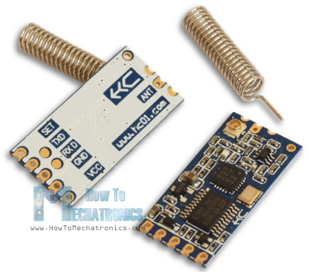
HC-12-Wireless-Serial-Communication-Module.jpg


HC-12无线通信模块

首先让我们仔细看看HC-12无线串口通信模块。以下是它的一些特性:

●    其无线工作频段为433.4 MHz至473.0 MHz

●    它有100个通道,每个通道之间的步进为400 KHz

●    发射功率从-1dBm(0.79mW)到20dBm(100mW)

●    接收灵敏度从-117dBm(0.019pW)到-100dBm(10pW)。


这些值实际上取决于所选的串行和空中波特率,如下表所示。
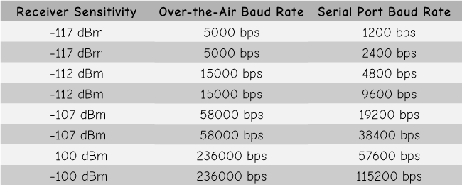
HC-12-Wireless-Module-Receiving-Sensitivity.png

HC-12模块有一个微控制器,实际上不需要由用户编程。对于配置模块,我们只需使用AT命令,可以从Arduino、PC或任何其他微控制器使用串口发送。要进入AT命令模式,我们只需将模块的“Set”引脚设置为低逻辑电平。


Arduino和HC-12

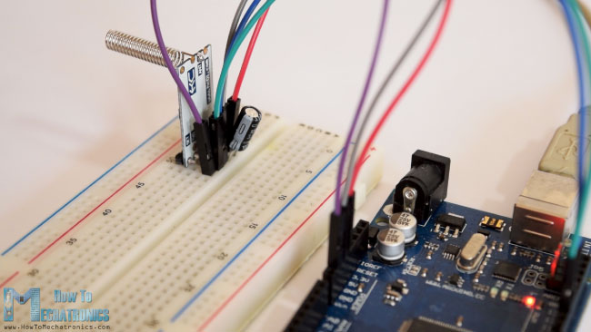
现在让我们将HC-12模块连接到Arduino并制作第一个示例。以下是电路原理图。模块的工作电压为3.2 V至5.5 V,为了更稳定工作,建议使用去耦电容和外部电源。但是,我使用PC USB作为本文章中所有三个示例的电源,并且没有任何问题。
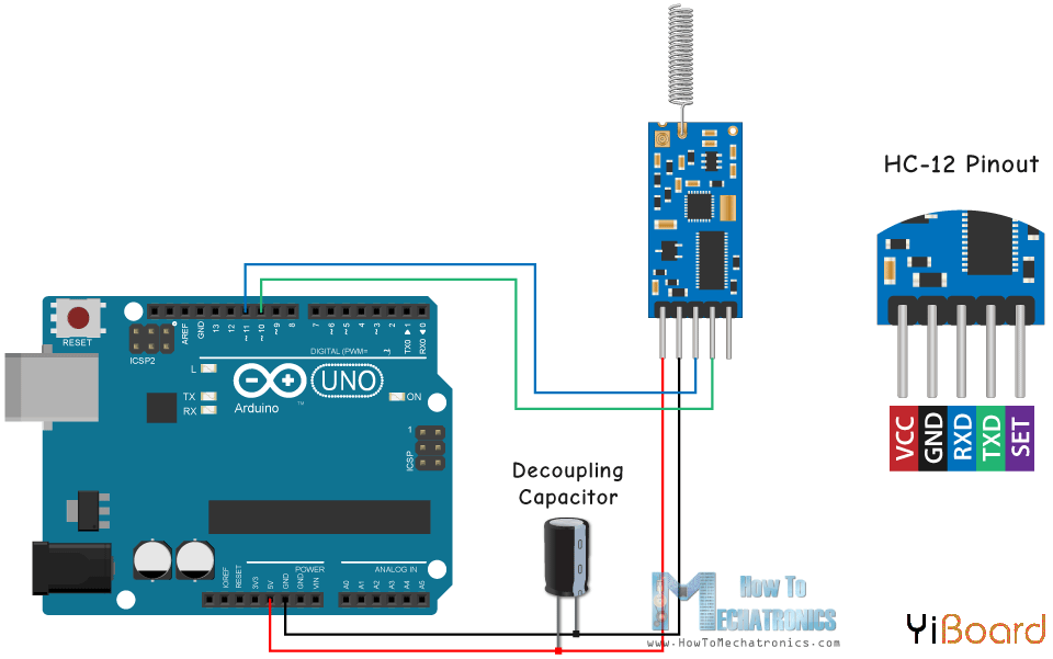
Arduino-and-HC-12-Circuit-Schematic.png

我将第一个模块连接到Arduino UNO开发板,将第二个模块连接到Arduino MEGA,您也可以使用任何您想要的开发板。

以下原理图所需的组件:

●    HC-12无线通信模块

●    Arduino开发板

●    面包板和跳线


示例01 - Arduino代码

以下是第一个示例的Arduino代码,使用串口监视器(Serial Monitor)在两个模块之间进行基本通信。

  1. /*    Arduino Long Range Wireless Communication using HC-12
  2.                       Example 01
  3.    by Dejan Nedelkovski, www.HowToMechatronics.com
  4. */
  5. #include <SoftwareSerial.h>
  6. SoftwareSerial HC12(10, 11); // HC-12 TX Pin, HC-12 RX Pin
  7. void setup() {
  8.   Serial.begin(9600);             // Serial port to computer
  9.   HC12.begin(9600);               // Serial port to HC12
  10. }
  11. void loop() {
  12.   while (HC12.available()) {        // If HC-12 has data
  13.     Serial.write(HC12.read());      // Send the data to Serial monitor
  14.   }
  15.   while (Serial.available()) {      // If Serial monitor has data
  16.     HC12.write(Serial.read());      // Send that data to HC-12
  17.   }
  18. }
复制代码

这两个Arduino开发板使用相同的代码。我们可以在两台独立的计算机上连接两个Arduino开发,但我们也可以使用一台计算机。
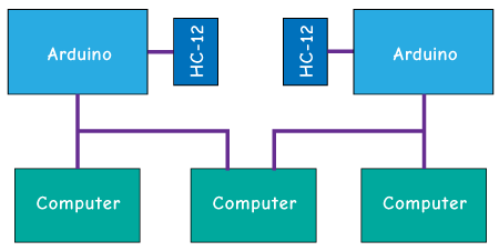
HC-12-to-PC.png

一旦我们将第一个Arduino开发板连接到计算机,我们需要选择型号和COM端口并将代码上传到Arduino。然后我们连接第二个Arduino,我们必须再次启动Arduino IDE,以便能够选择我们的第二个Arduino连接到的另一个COM端口,然后上传相同的代码。


因此,一旦我们运行了两个Arduino IDE,我们就可以启动串口监视器并测试通信是否正常工作。我们在串口监视器中输入的任何内容都将从一个发送到另一个Arduino。
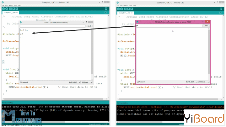
HC-12-Arduino-Serial-Communication-Example.png

代码如何工作:所以一旦我们在串口监视器中输入内容并单击Send按钮,在第一个Arduino上,while循环中的Seri​​al.available()函数将变为true,然后使用HC12.write()函数我们将数据从串行监视器发送到HC-12模块。该模块将数据无线传输到第二个HC-12模块,因此在第二个Arduino时,while循环中HC12.available()函数将变为true,然后使用Serial.write()函数将数据发送到串口监视器。

我们可以使用相同的代码发送AT命令和配置模块参数。我们所要做的就是将模块的“Set”引脚连接到地或Arduino的任何数字引脚,并将引脚设置为低逻辑电平。
HC-12-AT-Command-Set-Pin.jpg


为了测试我们是否已成功进入该模式,在串口监视器中我们可以输入“AT”,我们应该收到响应消息“OK”。总共有12个AT命令,它们用于改变波特率、通道、发射功率等各种参数。例如,如果输入“AT + B38400”,模块的波特率将设置为38400。


AT命令:

1. AT - 测试命令。

示例:向模块发送“AT”,模块返回“OK”。

2. AT + Bxxxx - 更改串口波特率。

可用波特率:1200 bps、2400 bps、4800 bps、9600 bps、19200 bps、38400 bps、57600 bps和115200 bps。默认值:9600 bps。

示例:将“AT + B38400”发送到模块,模块返回“OK + B19200”。

3. AT + Cxxxx - 更改无线通信信道,从001到100。

默认值:通道001,工作频率为433.4MHz。每个下一个通道都高出400KHz。

示例:如果我们要将模块设置为通道006,我们需要向模块发送“AT + C006”命令,模块将返回“OK + C006”。新的工作频率为435.4MHz。

跳转到指定楼层
风筝
发表于: 2018-11-17 08:58:31 | 显示全部楼层

示例02

现在让我们开始制作第二个例子。在该示例中,我们将使用两个按钮来选择不同的通信通道,并使用与以前不同的方法来存储传入的数据。

Example-02-HC-12-channels-selecting.jpg

注意:两个HC-12模块的“Set”引脚连接到两个Arduino的引脚6,第一个Arduino的两个按钮分别连接到引脚4和引脚3。


第一个Arduino开发板的代码:

  1. /*    Arduino Long Range Wireless Communication using HC-12
  2.     Example 02 - Changing channels using push buttons - Buttons side
  3.    by Dejan Nedelkovski, www.HowToMechatronics.com
  4. */
  5. #include <SoftwareSerial.h>
  6. #define setPin 6
  7. #define button1 4
  8. #define button2 3
  9. SoftwareSerial HC12(10, 11);         // HC-12 TX Pin, HC-12 RX Pin
  10. byte incomingByte;
  11. String readBuffer = "";
  12. int button1State = 0;
  13. int button1Pressed = 0;
  14. int button2State = 0;
  15. int button2Pressed = 0;
  16. void setup() {
  17.   Serial.begin(9600);                   // Open serial port to computer
  18.   HC12.begin(9600);                     // Open serial port to HC12
  19.   pinMode(setPin, OUTPUT);
  20.   pinMode(button1, INPUT);
  21.   pinMode(button2, INPUT);
  22.   digitalWrite(setPin, HIGH);           // HC-12 normal, transparent mode
  23. }
  24. void loop() {
  25.   // ==== Storing the incoming data into a String variable
  26.   while (HC12.available()) {             // If HC-12 has data
  27.     incomingByte = HC12.read();          // Store each icoming byte from HC-12
  28.     readBuffer += char(incomingByte);    // Add each byte to ReadBuffer string variable
  29.   }
  30.   delay(100);
  31.   // ==== Sending data from one HC-12 to another via the Serial Monitor
  32.   while (Serial.available()) {
  33.     HC12.write(Serial.read());
  34.   }
  35.   // ==== If button 1 is pressed, set the channel 01
  36.   button1State = digitalRead(button1);
  37.   if (button1State == HIGH & button1Pressed == LOW) {
  38.     button1Pressed = HIGH;
  39.     delay(20);
  40.   }
  41.   if (button1Pressed == HIGH) {
  42.     HC12.print("AT+C001");               // Send the AT Command to the other module
  43.     delay(100);
  44.     //Set AT Command Mode
  45.     digitalWrite(setPin, LOW);           // Set HC-12 into AT Command mode
  46.     delay(100);                          // Wait for the HC-12 to enter AT Command mode
  47.     HC12.print("AT+C001");               // Send AT Command to HC-12
  48.     delay(200);
  49.     while (HC12.available()) {           // If HC-12 has data (the AT Command response)
  50.       Serial.write(HC12.read());         // Send the data to Serial monitor
  51.     }
  52.     Serial.println("Channel successfully changed");
  53.     digitalWrite(setPin, HIGH);          // Exit AT Command mode
  54.     button1Pressed = LOW;
  55.   }
  56.   
  57.   // ====  If button 2 is pressed, set the channel 02
  58.   button2State = digitalRead(button2);
  59.   if (button2State == HIGH & button2Pressed == LOW) {
  60.     button2Pressed = HIGH;
  61.     delay(100);
  62.   }
  63.   if (button2Pressed == HIGH) {
  64.     HC12.print("AT+C002"); // Send the AT Command to the other module
  65.     delay(100);
  66.     //Set AT Command Mode
  67.     digitalWrite(setPin, LOW);           // Set HC-12 into AT Command mode
  68.     delay(100);                          // Wait for the HC-12 to enter AT Command mode
  69.     HC12.print("AT+C002");               // Send AT Command to HC-12
  70.     delay(200);
  71.     while (HC12.available()) {           // If HC-12 has data (the AT Command response)
  72.       Serial.write(HC12.read());         // Send the data to Serial monitor
  73.     }
  74.     Serial.println("Channel successfully changed");
  75.     digitalWrite(setPin, HIGH);
  76.     button2Pressed = LOW;
  77.   }
  78.   checkATCommand();
  79.   readBuffer = "";                       // Clear readBuffer
  80. }
  81. // ==== Custom function - Check whether we have received an AT Command via the Serial Monitor
  82. void checkATCommand () {
  83.   if (readBuffer.startsWith("AT")) {     // Check whether the String starts with "AT"
  84.     digitalWrite(setPin, LOW);           // Set HC-12 into AT Command mode
  85.     delay(200);                          // Wait for the HC-12 to enter AT Command mode
  86.     HC12.print(readBuffer);              // Send AT Command to HC-12
  87.     delay(200);
  88.     while (HC12.available()) {           // If HC-12 has data (the AT Command response)
  89.       Serial.write(HC12.read());         // Send the data to Serial monitor
  90.     }
  91.     digitalWrite(setPin, HIGH);          // Exit AT Command mode
  92.   }
  93. }
复制代码

第二个Arduino开发板的代码:

  1. /*    Arduino Long Range Wireless Communication using HC-12
  2.         Example 02 - Changing channels using push buttons
  3.    by Dejan Nedelkovski, www.HowToMechatronics.com
  4. */
  5. #include <SoftwareSerial.h>
  6. #define setPin 6
  7. SoftwareSerial HC12(10, 11); // HC-12 TX Pin, HC-12 RX Pin
  8. byte incomingByte;
  9. String readBuffer = "";
  10. void setup() {
  11.   Serial.begin(9600);             // Open serial port to computer
  12.   HC12.begin(9600);               // Open serial port to HC12
  13.   pinMode(setPin, OUTPUT);
  14.   digitalWrite(setPin, HIGH);     // HC-12 normal mode
  15. }
  16. void loop() {
  17.   // ==== Storing the incoming data into a String variable
  18.   while (HC12.available()) {             // If HC-12 has data
  19.     incomingByte = HC12.read();          // Store each icoming byte from HC-12
  20.     readBuffer += char(incomingByte);    // Add each byte to ReadBuffer string variable
  21.   }
  22.   delay(100);
  23.   // ==== Sending data from one HC-12 to another via the Serial Monitor
  24.   while (Serial.available()) {
  25.     HC12.write(Serial.read());
  26.   }
  27.   // === If button 1 is pressed, set channel 01
  28.   if (readBuffer == "AT+C001") {
  29.     digitalWrite(setPin, LOW);           // Set HC-12 into AT Command mode
  30.     delay(100);                          // Wait for the HC-12 to enter AT Command mode
  31.     HC12.print(readBuffer);              // Send AT Command to HC-12 ("AT+C001")
  32.     delay(200);
  33.     while (HC12.available()) {           // If HC-12 has data (the AT Command response)
  34.       Serial.write(HC12.read());         // Send the data to Serial monitor
  35.     }
  36.     Serial.println("Channel successfully changed");
  37.     digitalWrite(setPin, HIGH);          // Exit AT Command mode
  38.     readBuffer = "";
  39.   }
  40.   // === If button 2 is pressed, set channel 02
  41.   if (readBuffer == "AT+C002") {
  42.     digitalWrite(setPin, LOW);           // Set HC-12 into AT Command mode
  43.     delay(100);                          // Wait for the HC-12 to enter AT Command mode
  44.     HC12.print(readBuffer);              // Send AT Command to HC-12
  45.     delay(200);
  46.     while (HC12.available()) {           // If HC-12 has data (the AT Command response)
  47.       Serial.write(HC12.read());         // Send the data to Serial monitor
  48.     }
  49.     Serial.println("Channel successfully changed");
  50.     digitalWrite(setPin, HIGH);          // Exit AT Command mode
  51.     readBuffer = "";
  52.   }
  53.   checkATCommand();
  54.   readBuffer = "";                       // Clear readBuffer
  55. }
  56. // ==== Custom function - Check whether we have received an AT Command via the Serial Monitor
  57. void checkATCommand () {
  58.   if (readBuffer.startsWith("AT")) {     // Check whether the String starts with "AT"
  59.     digitalWrite(setPin, LOW);           // Set HC-12 into AT Command mode
  60.     delay(100);                          // Wait for the HC-12 to enter AT Command mode
  61.     HC12.print(readBuffer);              // Send AT Command to HC-12
  62.     delay(200);
  63.     while (HC12.available()) {           // If HC-12 has data (the AT Command response)
  64.       Serial.write(HC12.read());         // Send the data to Serial monitor
  65.     }
  66.     digitalWrite(setPin, HIGH);          // Exit AT Command mode
  67.   }
  68. }
复制代码

代码说明

首先我们需要定义引脚并将“Set”引脚设置为高逻辑电平,以使模块在正常的透明模式下工作。使用第一个while循环,我们将传入的数据存储到String变量中,这样我们可以更好地处理它。

  1. // ==== Storing the incoming data into a String variable
  2.   while (HC12.available()) {             // If HC-12 has data
  3.     incomingByte = HC12.read();          // Store each icoming byte from HC-12
  4.     readBuffer += char(incomingByte);    // Add each byte to ReadBuffer string variable
  5.   }
复制代码

传入的数据一次总是一个字节。举个例子,如果我们从第二个Arduino发送字符串“Test123”,这个while循环将进行7次迭代。每次迭代,使用HC12.read()函数,我们将读取每个传入的字节或字符,并将其添加到名为“readBuffer”的String变量中。

HC-12-Read-Buffer-Example-02.png

接下来让我们看看如何使用第一个按钮更改通信通道。因此,如果我们按下第一个按钮,使用HC12.print()函数,我们将字符串“AT + C001”发送到HC-12模块或第二个Arduino。

  1. if (button1Pressed == HIGH) {
  2.     HC12.print("AT+C001");               // Send the AT Command to the other module
  3.     delay(100);
  4.     //Set AT Command Mode
  5.     digitalWrite(setPin, LOW);           // Set HC-12 into AT Command mode
  6.     delay(100);                          // Wait for the HC-12 to enter AT Command mode
  7.     HC12.print("AT+C001");               // Send AT Command to HC-12
  8.     delay(200);
  9.     while (HC12.available()) {           // If HC-12 has data (the AT Command response)
  10.       Serial.write(HC12.read());         // Send the data to Serial monitor
  11.     }
  12.     Serial.println("Channel successfully changed");
  13.     digitalWrite(setPin, HIGH);          // Exit AT Command mode
  14.     button1Pressed = LOW;
  15.   }
复制代码

当在第二个Arduino接收到该字符串时,我们将HC-12模块设置为AT命令模式,然后将相同的字符串“AT + C001”写入其中,这将把模块设置为通信通道1。

  1. // At the second Arduino
  2. // === If button 1 is pressed, set channel 01
  3.   if (readBuffer == "AT+C001") {
  4.     digitalWrite(setPin, LOW);           // Set HC-12 into AT Command mode
  5.     delay(100);                          // Wait for the HC-12 to enter AT Command mode
  6.     HC12.print(readBuffer);              // Send AT Command to HC-12 ("AT+C001")
  7.     delay(200);
  8.     while (HC12.available()) {           // If HC-12 has data (the AT Command response)
  9.       Serial.write(HC12.read());         // Send the data to Serial monitor
  10.     }
  11.     Serial.println("Channel successfully changed");
  12.     digitalWrite(setPin, HIGH);          // Exit AT Command mode
  13.     readBuffer = "";
  14.   }
复制代码

我们使用下一个while循环来打印来自HC-12模块的响应消息,无论通道是否已成功更改。

  1. while (HC12.available()) {           // If HC-12 has data (the AT Command response)
  2.       Serial.write(HC12.read());         // Send the data to Serial monitor
  3.     }
复制代码

回到第一个Arduino,我们执行将AT命令发送到第一个HC-12模块的相同过程。以同样的方式,我们使用按下第二个按钮,我们设置通信通道2。因此,使用此方法,我们可以随时选择与之沟通的HC-12模块。


最后,checkATCommand()自定义函数通过检查字符串是否以“AT”开头来检查收到的消息是否是AT命令。如果是,则模块进入AT命令模式并执行命令。

  1. // ==== Custom function - Check whether we have received an AT Command via the Serial Monitor
  2. void checkATCommand () {
  3.   if (readBuffer.startsWith("AT")) {     // Check whether the String starts with "AT"
  4.     digitalWrite(setPin, LOW);           // Set HC-12 into AT Command mode
  5.     delay(200);                          // Wait for the HC-12 to enter AT Command mode
  6.     HC12.print(readBuffer);              // Send AT Command to HC-12
  7.     delay(200);
  8.     while (HC12.available()) {           // If HC-12 has data (the AT Command response)
  9.       Serial.write(HC12.read());         // Send the data to Serial monitor
  10.     }
  11.     digitalWrite(setPin, HIGH);          // Exit AT Command mode
  12.   }
  13. }
复制代码

回复

使用道具 举报

风筝
发表于: 2018-11-17 09:30:08 | 显示全部楼层

HC-12无线通信:使用加速度计控制步进电机

现在来看看第三个例子。本示例中,我们使用第一个Arduino开发板上的加速度计模块控制第二个Arduino上的步进电机的位置。

HC-12-Wireless-Communication-Stepper-Motor-Control-using-an-Accelerometer-Example-03.jpg

该电路还包含一个微动开关,用于查出步进电机的初始位置为0度。

HC-12-Wireless-Communication-Stepper-Motor-Control-using-an-Accelerometer-Circui.png


此示例所需的组件如下:

●    HC-12无线通信模块

●    A4988步进电机驱动器

●    步进电机NEMA 17

●    Arduino开发板

●    面包板和跳线

●    带ADXL345加速度计的GY-80电路板


第一个Arduino - 发射器代码:

  1. /*   Arduino Long Range Wireless Communication using HC-12
  2.      Example 03 - Stepper Motor Control using Accelerometer - Transmitter, Accelerometer
  3.     by Dejan Nedelkovski, www.HowToMechatronics.com
  4. */
  5. #include <SoftwareSerial.h>
  6. #include <Wire.h>
  7. SoftwareSerial HC12(10, 11); // HC-12 TX Pin, HC-12 RX Pin
  8. float angle;
  9. int lastAngle = 0;
  10. int count = 0;
  11. int angleSum = 0;
  12. //--- Accelerometer Register Addresses
  13. #define Power_Register 0x2D
  14. #define X_Axis_Register_DATAX0 0x32 // Hexadecima address for the DATAX0 internal register.
  15. #define X_Axis_Register_DATAX1 0x33 // Hexadecima address for the DATAX1 internal register.
  16. #define Y_Axis_Register_DATAY0 0x34
  17. #define Y_Axis_Register_DATAY1 0x35
  18. #define Z_Axis_Register_DATAZ0 0x36
  19. #define Z_Axis_Register_DATAZ1 0x37
  20. int ADXAddress = 0x53;  //Device address in which is also included the 8th bit for selecting the mode, read in this case.
  21. int X0, X1, X_out;
  22. int Y0, Y1, Y_out;
  23. int Z1, Z0, Z_out;
  24. float Xa, Ya, Za;
  25. void setup() {
  26.   HC12.begin(9600);               // Open serial port to HC12
  27.   Wire.begin(); // Initiate the Wire library
  28.   Serial.begin(9600);
  29.   delay(100);
  30.   Wire.beginTransmission(ADXAddress);
  31.   Wire.write(Power_Register); // Power_CTL Register
  32.   // Enable measurement
  33.   Wire.write(8); // Bit D3 High for measuring enable (0000 1000)
  34.   Wire.endTransmission();
  35. }
  36. void loop() {
  37.   // X-axis
  38.   Wire.beginTransmission(ADXAddress); // Begin transmission to the Sensor
  39.   //Ask the particular registers for data
  40.   Wire.write(X_Axis_Register_DATAX0);
  41.   Wire.write(X_Axis_Register_DATAX1);
  42.   Wire.endTransmission(); // Ends the transmission and transmits the data from the two registers
  43.   Wire.requestFrom(ADXAddress, 2); // Request the transmitted two bytes from the two registers
  44.   if (Wire.available() <= 2) { //
  45.     X0 = Wire.read(); // Reads the data from the register
  46.     X1 = Wire.read();
  47.     /* Converting the raw data of the X-Axis into X-Axis Acceleration
  48.       - The output data is Two's complement
  49.       - X0 as the least significant byte
  50.       - X1 as the most significant byte */
  51.     X1 = X1 << 8;
  52.     X_out = X0 + X1;
  53.     Xa = X_out / 256.0; // Xa = output value from -1 to +1, Gravity acceleration acting on the X-Axis
  54.   }
  55.   //Serial.print("Xa= ");
  56.   //Serial.println(X_out);
  57.   // Y-Axis
  58.   Wire.beginTransmission(ADXAddress);
  59.   Wire.write(Y_Axis_Register_DATAY0);
  60.   Wire.write(Y_Axis_Register_DATAY1);
  61.   Wire.endTransmission();
  62.   Wire.requestFrom(ADXAddress, 2);
  63.   if (Wire.available() <= 2) {
  64.     Y0 = Wire.read();
  65.     Y1 = Wire.read();
  66.     Y1 = Y1 << 8;
  67.     Y_out = Y0 + Y1;
  68.     Ya = Y_out / 256.0;
  69.   }
  70.   // Combine X and Y values for getting the angle value from 0 to 180 degrees
  71.   if (Y_out > 0) {
  72.     angle = map(Y_out, 0, 256, 90, 0);
  73.   }
  74.   else if (Y_out < 0) {
  75.     angle = map(Y_out, 256, 0, 90, 0);
  76.     angle = 90 - angle;
  77.   }
  78.   if (X_out < 0 & Y_out < 0) {
  79.     angle = 180;
  80.   }
  81.   if (X_out < 0 & Y_out >0) {
  82.     angle = 0;
  83.   }
  84.   
  85.   // float to int
  86.   int angleInt = int(angle);
  87.   // Makes 100 accelerometer readings and sends the average for smoother result
  88.   angleSum = angleSum + angleInt;
  89.   count++;
  90.   if (count >= 100) {
  91.     angleInt = angleSum / 100;
  92.     angleSum = 0;
  93.     count = 0;
  94.     // Some more smoothing of acceleromter reading - sends the new angle only if it differes from the previous one by +-2
  95.     if (angleInt > lastAngle + 2 || angleInt < lastAngle - 2) {
  96.       Serial.println(angleInt);
  97.       String angleString = String(angleInt);
  98.       //sends the angle value with start marker "s" and end marker "e"
  99.       HC12.print("s" + angleString + "e");
  100.       delay(10);
  101.       lastAngle = angleInt;
  102.       angleSum = 0;
  103.       count = 0;
  104.     }
  105.   }
  106. }
复制代码

第二个Arduino - 接收器代码:

  1. /*   Arduino Long Range Wireless Communication using HC-12
  2.      Example 03 - Stepper Motor Control using Accelerometer - Receiver, Stepper Motor
  3.     by Dejan Nedelkovski, www.HowToMechatronics.com
  4. */
  5. #include <SoftwareSerial.h>
  6. SoftwareSerial HC12(10, 11); // HC-12 TX Pin, HC-12 RX Pin
  7. char incomingByte;
  8. String readBuffer = "";
  9. // defines pins numbers
  10. const int dirPin = 4;
  11. const int stepPin = 3;
  12. const int button = 2;
  13. int currentAngle = 0;
  14. int lastAngle = 0;
  15. int rotate = 0;
  16. void setup() {
  17.   Serial.begin(9600);             // Open serial port to computer
  18.   HC12.begin(9600);               // Open serial port to HC12
  19.   // Sets the two pins as Outputs
  20.   pinMode(dirPin, OUTPUT);
  21.   pinMode(stepPin, OUTPUT);
  22.   // Microswitch input, with internal pull-up resistor activated
  23.   pinMode(button, INPUT_PULLUP);
  24.   delay(10);
  25.   digitalWrite(dirPin, HIGH);
  26.   boolean startingPosition = true;
  27.   while (startingPosition) {
  28.     digitalWrite(stepPin, HIGH);
  29.     delayMicroseconds(200);
  30.     digitalWrite(stepPin, LOW);
  31.     delayMicroseconds(200);
  32.     if (digitalRead(button) == LOW) {
  33.       startingPosition = false;
  34.     }
  35.   }
  36.   delay(100);
  37. }
  38. void loop() {
  39.   readBuffer = "";
  40.   boolean start = false;
  41.   // Reads the incoming angle
  42.   while (HC12.available()) {             // If HC-12 has data
  43.     incomingByte = HC12.read();          // Store each icoming byte from HC-12
  44.     delay(5);
  45.     // Reads the data between the start "s" and end marker "e"
  46.     if (start == true) {
  47.       if (incomingByte != 'e') {
  48.         readBuffer += char(incomingByte);    // Add each byte to ReadBuffer string variable
  49.       }
  50.       else {
  51.         start = false;
  52.       }
  53.     }
  54.     // Checks whether the received message statrs with the start marker "s"
  55.     else if ( incomingByte == 's') {
  56.       start = true; // If true start reading the message
  57.     }
  58.   }
  59.   // Converts the string into integer
  60.   currentAngle = readBuffer.toInt();
  61.   // Makes sure it uses angles between 0 and 180
  62.   if (currentAngle > 0 && currentAngle < 180) {
  63.     // Convert angle value to steps (depending on the selected step resolution)
  64.     // A cycle = 200 steps, 180deg = 100 steps ; Resolution: Sixteenth step x16
  65.     currentAngle = map(currentAngle, 0, 180, 0, 1600);
  66.     //Serial.println(currentAngle); // Prints the angle on the serial monitor
  67.     digitalWrite(dirPin, LOW); // Enables the motor to move in a particular direction
  68.     // Rotates the motor the amount of steps that differs from the previous positon
  69.     if (currentAngle != lastAngle) {
  70.       if (currentAngle > lastAngle) {
  71.         rotate = currentAngle - lastAngle;
  72.         for (int x = 0; x < rotate; x++) {
  73.           digitalWrite(stepPin, HIGH);
  74.           delayMicroseconds(400);
  75.           digitalWrite(stepPin, LOW);
  76.           delayMicroseconds(400);
  77.         }
  78.       }
  79.       // rotate the other way
  80.       if (currentAngle < lastAngle) {
  81.         rotate = lastAngle - currentAngle;
  82.         digitalWrite(dirPin, HIGH);        //Changes the rotations direction
  83.         for (int x = 0; x < rotate; x++) {
  84.           digitalWrite(stepPin, HIGH);
  85.           delayMicroseconds(400);
  86.           digitalWrite(stepPin, LOW);
  87.           delayMicroseconds(400);
  88.         }
  89.       }
  90.     }
  91.     lastAngle = currentAngle;  // Remembers the current/ last positon
  92.   }
  93. }
复制代码

代码说明

首先,我们在setup函数部分定义引脚并初始化模块。然后我们读取加速度计的X和Y轴的值,并将它们映射到0到180度的值。来自加速度计的值有时可能不稳定或抖动,因此为了平滑结果,我使用了100个读数的平均值。

  1. // Makes 100 accelerometer readings and sends the average for smoother result
  2.   angleSum = angleSum + angleInt;
  3.   count++;
  4.   if (count >= 100) {
  5.     angleInt = angleSum / 100;
  6.     angleSum = 0;
  7.     count = 0;
  8.     // Some more smoothing of acceleromter reading - sends the new angle only if it differes from the previous one by +-2
  9.     if (angleInt > lastAngle + 2 || angleInt < lastAngle - 2) {
  10.       Serial.println(angleInt);
  11.       String angleString = String(angleInt);
  12.       //sends the angle value with start marker "s" and end marker "e"
  13.       HC12.print("s" + angleString + "e");
  14.       delay(10);
  15.       lastAngle = angleInt;
  16.       angleSum = 0;
  17.       count = 0;
  18.     }
  19.   }
复制代码

为了进一步平滑,只有当角度值与之前的值大于2时,我才会发送角度的新值。


请注意,当将角度值发送到HC-12模块时,我也会在前面发送字符“s”,以及后面发送字符“e”,这将在第二个Arduino接收数据时有所帮助。


在第二个Arduino开发板中,我们等到开始标记“s”到来,然后我们读取角度的值,直到结束标记“e”到达。这样我们就可以确保只收到角度的值。

  1. // Reads the incoming angle
  2.   while (HC12.available()) {             // If HC-12 has data
  3.     incomingByte = HC12.read();          // Store each icoming byte from HC-12
  4.     delay(5);
  5.     // Reads the data between the start "s" and end marker "e"
  6.     if (start == true) {
  7.       if (incomingByte != 'e') {
  8.         readBuffer += char(incomingByte);    // Add each byte to ReadBuffer string variable
  9.       }
  10.       else {
  11.         start = false;
  12.       }
  13.     }
  14.     // Checks whether the received message statrs with the start marker "s"
  15.     else if ( incomingByte == 's') {
  16.       start = true; // If true start reading the message
  17.     }
  18.   }
复制代码

然后我们将值转换为整数,并将值映射为0到1600步,这对应于A4988步进驱动程序中选定的第16步分辨率。然后我们将步进电机旋转到当前角度。


以上就是本篇文章的全部内容。如果遇到问题,请随时在下面进行回复。

回复

使用道具 举报

zhp
发表于: 2019-5-4 22:19:59 | 显示全部楼层

很有启发!谢谢楼主,但没有附件下载哟
回复

使用道具 举报

您需要登录后才可以回帖 登录 | 立即注册

本版积分规则

主题 714 | 回复: 1501


手机版|

GMT+8, 2024-12-22 21:18 , Processed in 0.041383 second(s), 6 queries , Gzip On, MemCache On. Powered by Discuz! X3.5

YiBoard一板网 © 2015-2022 地址:河北省石家庄市长安区高营大街 ( 冀ICP备18020117号 )

快速回复 返回顶部 返回列表