|
本篇文章主要介绍了EFM8微控制器与DAC和MAX31855进行通信的固件代码。 该PID(比例 - 积分 - 微分)温度控制系统的主要组件包含EFM8微控制器、DAC和MAX31855热电偶数字转换器。该系列总共有6部分: ● Part 1:电路原理设计 ● Part 2:板级集成
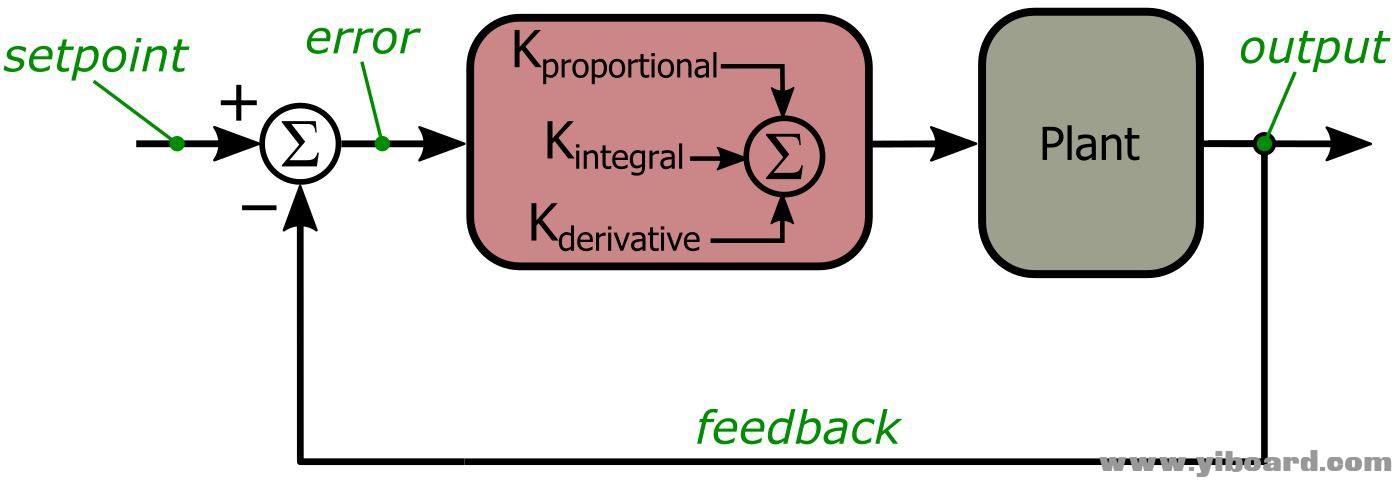
硬件设计 在上一篇文章中,我们介绍了PID控制系统的示意图:

从该图中我们可以看到建立PID系统需要三个基本组件:执行PID计算的控制器;将控制器的计算转化为物理变化的执行器;以及反馈机制,将物理变化转换回模拟或数字信号,可用于控制器的计算。在我们的PID恒温器中,这三个组件分别对应于EFM8微控制器、带大电流驱动电路的DAC以及MAX31855热电偶数字转换器。因此,项目的成功取决于是否有可靠的通信,能够将这三个功能块集成到一个统一的PID系统中。
SPI通信 实际上,SPI表示串行外设接口(Serial Peripheral Interface)。SPI是一种简单、灵活、低资源的通信协议,市场上的每个微控制器和DSP都可以支持这种协议。而且,幸运的是,MAX31855和DAC都支持SPI。但是,SPI不是固定的、精确定义的协议;它更像是一个串行通信的通用方法。标准功能如下: ● 总线上的每个设备都是主机设备或从机设备。 (可能有多个主设备,但我建议尽可能避免这种情况。对于多主机系统,最好选择I2C。) ● 电气连接包括串行时钟信号(SCK)、主机到从机数据信号(MOSI,即主机输出从机输入)、从机到主机数据信号(MISO,即主机输入从机输出)和每个从设备的一个从机选择信号(NSS)。 ● 主机通过激活一条或多条NSS连接线以及在SCK上驱动时钟脉冲来启动所有事务。只要NSS处于活动状态,事务就会继续。 ● 事务可以涉及从主设备到从设备(通过MOSI)、从从设备到主设备(通过MISO)或两者的数据传输。主设备可以通过激活所有NSS线路将数据发送到多个从机设备,但为了避免驱动程序争用,从设备必须采用一些共享MISO信号的方法。
以下原理图显示了SPI总线上器件的硬件设计。

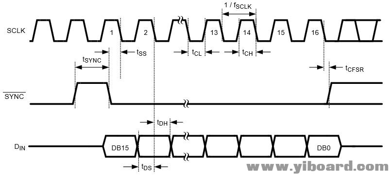
精确的传输时间 以下两张图展示了总线上两个从设备的SPI时序的详细信息。第一张来自MAX31855的数据手册,第二张来自于DAC的数据手册。


在MAX31855的图中,使用CS代替NSS。 CS表示“芯片选择(chip select)”,上划线表示其有效状态为逻辑低电平;NSS代表“非从机选择(not slave select)”,其中“非”(而不是采用上划线)表示它是低电平有效信号。
在DAC的图中,使用带有上划线的SYNC而不是NSS,但在这种情况下情况稍微复杂一些。 DAC旨在兼容各种串行通信协议;这就是为什么时序图看起来不像典型的SPI。但典型的SPI工作正常,这就是我们将要使用的时序。
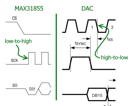
如果你仔细观察这两个图,你会发现一个小但重要的差异:对于MAX31855,NSS下降沿之后的第一个时钟转换是从低到高的转换。而对于DAC,它是一个从高到低的转换:

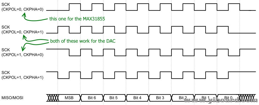
这意味着我们需要根据正在与哪个从机通信来调整EFM8的SPI配置。下图说明了EFM8控制器的SPI外设提供的四种时钟配置选项;只需将设备的时序详细信息与此图进行比较,即可确定正确的配置。

组合数据 SPI是一种可延展的协议,这不仅适用于时序细节,也适用于数据格式化。 MAX31855将数据作为一个32位字传输,如下所示:

我们不用担心这个项目的错误处理,不需要知道MAX31855的内部温度,因此我们需要的所有信息都包含在前14位(位31到位18)中。但是,EFM8的SPI外设以字节为单位工作,因此我们将从MAX31855读取两个字节,然后忽略两个最低有效位。
从MAX31855读取数据的过程从一个名为GatherTempData()的函数开始,然后是一个结合到SPI中断服务程序中的简单状态机。以下代码摘录中的注释和描述性标识符可帮助您了解MAX31855接口的固件详细信息。 - void GatherTempData(void)
- {
- //ensure that we are not interrupting an ongoing transmission
- while(SPI_State != IDLE);
- SPI0CN0_SPIEN = 0; //disable SPI so we can change the clock configuration
- SPI0CFG &= ~SPI0CFG_CKPOL__BMASK; //set clock phase for the MAX31855 interface
- SPI0CFG &= ~SPI0CFG_CKPHA__BMASK; //set clock polarity for the MAX31855 interface
- SPI0CN0_SPIEN = 1; //re-enable SPI
- TC_NSS = LOW; //activate MAX31855 slave select
- /*We need to write a dummy byte to initiate the SPI transaction.
- * We do not need to send any data to the MAX31855; rather,
- * writing to the SPI0DAT register forces the EFM8 to generate
- * the clock pulses that cause the MAX31855 to transmit data.*/
- SPI0DAT = 0x00;
- SPI_State = FIRST_TC_BYTE_SENT;
- }
- SI_INTERRUPT (SPI0_ISR, SPI0_IRQn)
- {
- //SPI registers are on all SFR pages, so need need to modify SFRPAGE
- SPI0CN0_SPIF = 0; //clear interrupt flag
- switch(SPI_State)
- {
- //SPI communications with thermocouple IC====================================
- case FIRST_TC_BYTE_SENT:
- RawTempData = SPI0DAT;
- SPI0DAT = 0x00; //write a second dummy byte so that the MAX31855 will continue transmitting
- SPI_State = SECOND_TC_BYTE_SENT;
- break;
- case SECOND_TC_BYTE_SENT:
- TC_NSS = HIGH; //disable slave select
- RawTempData = (RawTempData << 8) | SPI0DAT;
- /* The following instructions convert the raw
- * binary temperature data into a format that
- * both Scilab and the EFM8 can easily convert
- * into a floating point number.*/
- TempData[0] = LOWBYTE(RawTempData >> 12);
- TempData[1] = LOWBYTE(RawTempData >> 4);
- switch((RawTempData & (BIT3|BIT2)) >> 2)
- {
- case 0: TempData[2] = 0;
- break;
- case 1: TempData[2] = 25;
- break;
- case 2: TempData[2] = 50;
- break;
- case 3: TempData[2] = 75;
- break;
- }
- TEMP_DATA_READY = TRUE;
- SPI_State = IDLE;
- break;
- //SPI communications with DAC===========================================
- case FIRST_DAC_BYTE_SENT:
- SPI0DAT = UpdateDAC_SecondByte;
- SPI_State = SECOND_DAC_BYTE_SENT;
- break;
- case SECOND_DAC_BYTE_SENT:
- DAC_NSS = HIGH; //disable slave select
- SPI_State = IDLE;
- break;
- }
- }
DAC传输的是一个16位字长,如下所示:

我们将发送两个连续的字节,DAC将其认为为一个16位字。 加热器驱动电路连接到DAC通道D,因此前两位将是二进制11。我们项目采用的正确更新模式是“写入指定寄存器并更新输出(write to specified register and update outputs)”,因此第三和第四位将是二进制01。与MAX31855接口一样,DAC事务以UpdateDAC()函数开始,然后是SPI状态机。 - void UpdateDAC(unsigned char ChannelABCorD, unsigned char DACcode)
- {
- //ensure that we are not interrupting an ongoing transmission
- while(SPI_State != IDLE);
- /*This switch statement sets the two most significant bits of the 16-bit DAC word
- * according to which channel is being updated. It also sets the two "operation mode"
- * bits to binary 01, which corresponds to "write to specified register and
- * update outputs."*/
- switch(ChannelABCorD)
- {
- case DAC_CH_A:
- UpdateDAC_FirstByte = 0x10;
- break;
- case DAC_CH_B:
- UpdateDAC_FirstByte = 0x50;
- break;
- case DAC_CH_C:
- UpdateDAC_FirstByte = 0x90;
- break;
- case DAC_CH_D:
- UpdateDAC_FirstByte = 0xD0;
- break;
- }
- /*The upper four bits of the DAC code are the lower four bits
- * of the first byte, and the lower four bits of the DAC code are
- * the upper four bits of the second byte.*/
- UpdateDAC_FirstByte = UpdateDAC_FirstByte | (DACcode >> 4);
- UpdateDAC_SecondByte = DACcode << 4;
- SPI0CN0_SPIEN = 0; //disable SPI so we can change the clock configuration
- SPI0CFG |= SPI0CFG_CKPOL__BMASK; //set clock phase for the DAC interface
- SPI0CFG &= ~SPI0CFG_CKPHA__BMASK; //set clock polarity for the DAC interface
- SPI0CN0_SPIEN = 1; //re-enable SPI
- DAC_NSS = LOW; //activate DAC slave select
- SPI0DAT = UpdateDAC_FirstByte;
- SPI_State = FIRST_DAC_BYTE_SENT;
- }
固件 以下只是一个测试程序,通过反复递增加载到DAC通道D的8位值,将加热器驱动电压从0 V变化到大约2.4 V: - int main(void)
- {
- unsigned char Heater_Drive;
- //call hardware initialization routine
- enter_DefaultMode_from_RESET();
- //enable global interrupts
- IE_EA = 1;
- Heater_Drive = 0;
- //refer to the PCA ISR for information on the delay functionality
- PCA0 = 0x0000 - PID_INTERVAL;
- PCA0CN0_CR = PCA_RUN;
- while (1)
- {
- PID_WAIT = TRUE;
- while(PID_WAIT == TRUE);
- UpdateDAC(DAC_HEATER, Heater_Drive);
- Heater_Drive++;
- }
- }
DAC更新之间的延迟 - 称为“PID间隔”,因为我们将使用与实际PID控制器相同的延迟功能 - 通过将Timer0配置为以1 kHz的频率溢出来实现,然后使用Timer0溢出作为可编程计数器阵列(PCA)的时钟源,使得16位PCA计数器/定时器寄存器每毫秒递增一次。 - SI_INTERRUPT (PCA0_ISR, PCA0_IRQn)
- {
- //PCA registers are on all SFR pages, so no need to modify SFRPAGE
- PCA0CN0_CF = 0; //clear interrupt flag
- /*The overflow interrupt fires when the PCA counter/timer
- * overflows from 0xFFFF to 0x0000, so we create the delay
- * as follows:*/
- PCA0 = 0x0000 - PID_INTERVAL; //PID_INTERVAL is the delay in milliseconds
- PID_WAIT = FALSE;
- }
总结 现在我们已经将三个PID组件转变为一个不会停止的的、无缝集成的温度控制系统。 在下一篇文章中,我们将实现一个简单的嵌入式PID算法,并使用示波器测量和可变强度LED来观察系统的功能。 |  |手机版|YiBoard一板网
( 冀ICP备18020117号 )